


Geotechnical protection of a deep excavation at the «Multistorey residential complex with elements of social infrastructure on Parallelnaya Street, 9 in Sochi»
Client– «RGS-Real Estate»
Head engineer – O. Eschenko
Head structural engineer – M. Marinichev
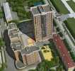
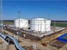
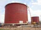
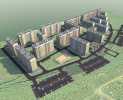
The construction site is located in the central district of Sochi. It’s situated south-east of the railway station, on the territory of the former tank farm. From the north, the work site is limited be the Volgogradskaya street, from the south, west and east by Parallelnaya Street.In the beginning the site was free from construction. The existing development of the adjacent areas is represented by one-two-story private and low-rise (up to 5-6 floors) municipal buildings.
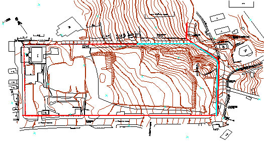
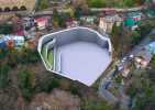
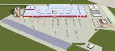
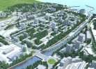
Fig. 1. Layout of the construction site
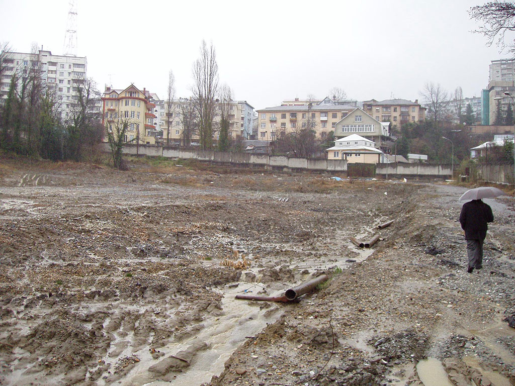
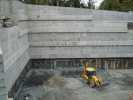
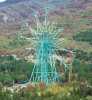
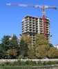
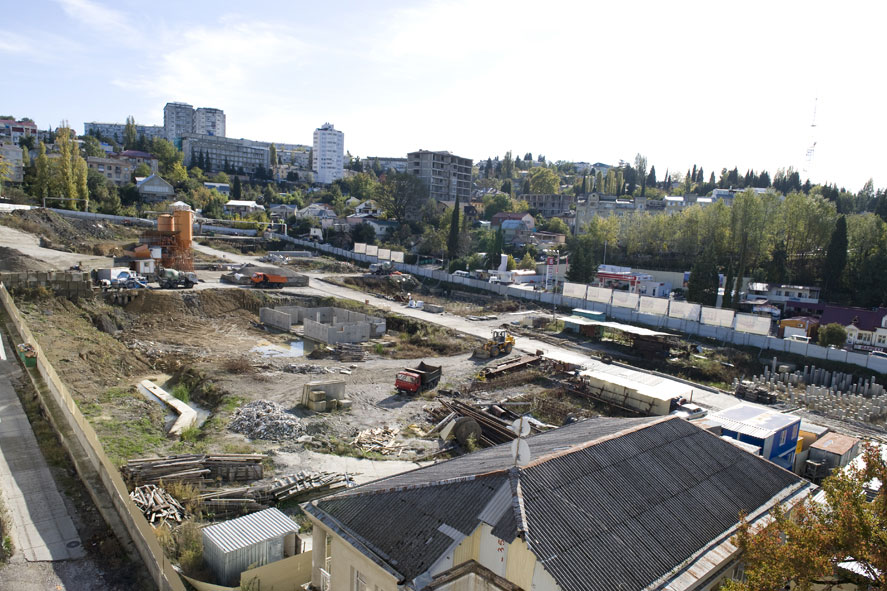
Fig. 2. Construction site. View from the center in an easterly direction
For engineering protection of the construction site it was necessary to develop an landslide protection along the north-eastern and south-eastern sides of the excavation.
The designed structure must meet the following requirements:
- The structures must ensure protection of the excavation from underflooding and flooding with groundwater.
- The structure should have a minimum width, since it should not extend beyond the boundary of the land allocation.
- Along the southeast side (in particular - in the eastern corner) the pit has a considerable depth. Here, the structure should be reinforced with one or more tiers of anchors.
- Anchors should be embedded in the grounds of the IGE-4 from the northeast and in the IGE-5 - from the southeast side of the excavation (from the side of the ancient landslide).
- In order to ensure a reliable closure of the structure below the design mark of the excavation of the excavation, the holding structure must be buried in the bedrock of IGE-4 or IGE-5.
- It is necessary to provide for measures to protect the structures of the containment structures from aggressive underground waters.
- In the eastern corner of the excavation, it is necessary to provide for turning the anchors in plan relative to the normal to the structure for leaving the spot of the building projected here. According to preliminary analysis, the angle of rotation of anchors in the plan is about 23 degrees.
Considering the dense construction of the site, the customer was assigned a narrow strip along the border of the land for the placement of engineering protection facilities and construction works. Within this strip (1-1.5 m), to keep the vertical wall of the pit from 10 to 16 m deep, it is inevitable to use ground anchors or horizontal struts.
Since, according to the survey materials, there is a presence on the site of pressure (and in the central part - artesian) waters, in order to ensure the conditions for the production of construction works, the design of engineering protection must also protect the excavation from groundwater.
In addition, along the edge of the excavation, intensive movement of heavily laden transport is envisaged (both during the construction period and at the stage of operation).
Taking into account the above factors, the main design of the containment structures was a wall, reinforced with anchors.
According to the requirements, the following restrictions were revealed:
- The site is potentially landslide (a deep trench can provoke a landslide);
- the soils of the upper IGE are filtering unstable against the action of pressure waters (the walls of the trench can collapse);
- the groundwater level approaches closer than 1.5 m to the surface of the trench device (on the site there are wells with self-pouring water);
- there are no surveys along the perimeter of the wall with a step of wells not exceeding 20 m and a depth of 10 m greater than the depth of the wall;
- the relief has a significant slope and the project provides for the installation of an inclined grillage inscribed in the relief;
- Sedimentary and semicluster soils are located within the design depth of the wall structure, which complicates the production of one equipment
In this regard, the project provides for the construction of a wall made of piles arranged under the protection of the extracted casing pipes.
As a ground anchors, the project provides for the use of anchors of the type TITAN 103/78 by Ischebeck.
In the course of stability calculations on the protected site, the following basic design situations were considered:
- The natural state of the slope at the time of investigation.
- The main combination of loads. Transport load along the carriageway of adjacent streets
- A special combination of loads, taking into account seismic influences up to 8 points.
- Forecast condition of the slope for the period of construction of the facility, taking into account excavation of the excavation to project marks.
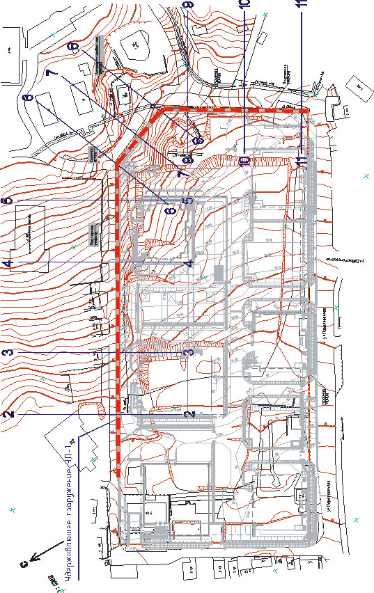
Fig. 3. The construction site of a multi-storey residential building on the street. Parallel, 9 in Sochi. Scheme of the location of the calculated alignments
The physical and mechanical characteristics of the soils and the level of groundwater were taken according to engineering and geological surveys. Strength properties of the soil according to the scheme of consolidated water-saturated shift. In the roof of the ground soils of the IGE-5, a decompacted fractured layer with a thickness of 2.5 m was isolated. The strength properties of the separated layer were taken from the data of Table 1. The underlying bedrock was taken into account as rock unbiased soils.
Estimated loads on slopes were taken based on the results of studying topographic material and in accordance with the requirements of the relevant chapters of SNiP:
- Transport load along the carriageway of adjacent streets was assumed equal to 40 kPa across the entire width of the road. In addition, the load on the roadside is taken into account, at a distance of 1 m from the side of the excavation. The total bandwidth of the load is 7 m.
- The load from the buildings was assumed to be 10-15 kPa per floor, taking into account the coefficient of bringing the real load area to the area of the strip load along the width between adjacent sections.
- Load from structures, cars and materials located on the slope was taken into account equal to 10 kPa along the entire length of the slope.
Calculations of slope stability in the calculated situation 1 were carried out by the method of general limit equilibrium. The slope stability was evaluated by the finite element method.
Calculations of the structures of the anti-landslide holding structure to hold the soil on the sides of the foundation pit were made taking into account its phased construction and the construction of the protected object. The calculations also take into account the effect of predictive adverse events such as high standing of the groundwater level, seismic impacts up to 8 points and the transport load along the side of the pit, both during the construction period and the operation of the facility.
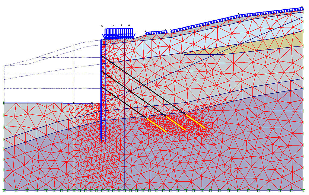
Fig. 4. Fragment of the scheme to the calculation of structures in section 7-7. Stage of excavation to the design marks of the excavation
After analyzing various technical options, including anchorages and horizontal spacers in the form of spatial frames, we came to the option of building a foundation pit without the use of ground anchors, which fell within the compressible thickness of the nearby high-rise building.
The chosen version of protection device included a sequence of interrelated technological stages, where for the construction period the ground pressure is perceived by a temporary spatial frame, and as the underground garages were built, the pressure was transferred to the building structures.
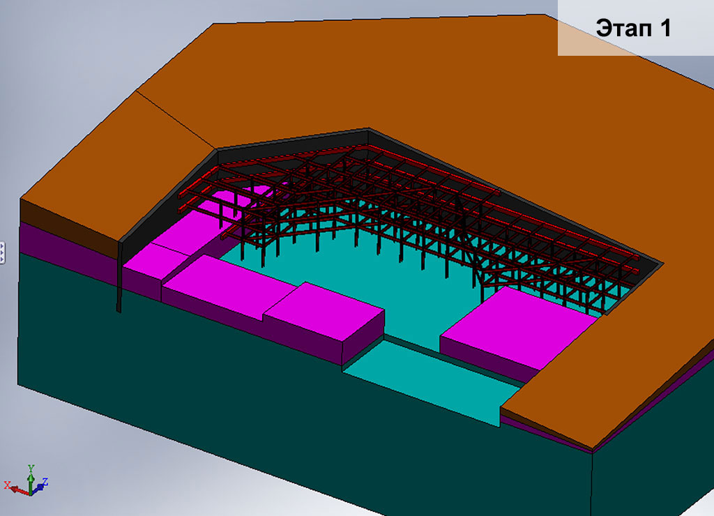
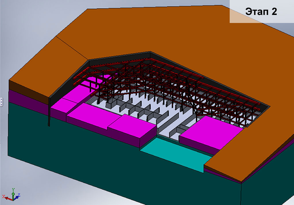
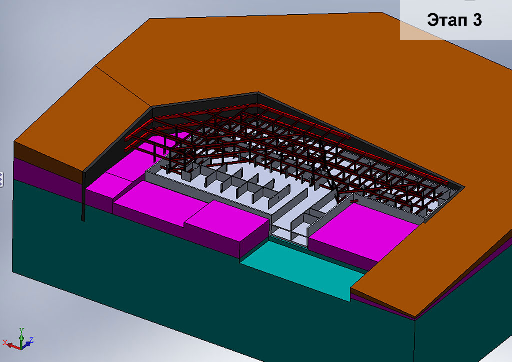
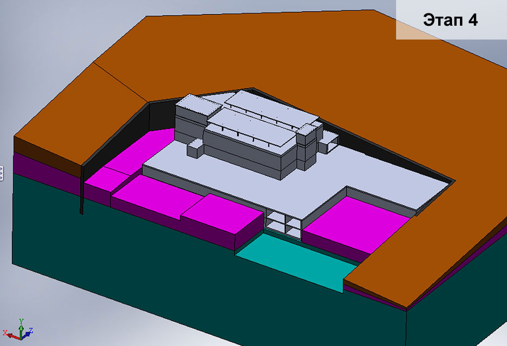
Fig. 5. The sequence of technological and design stages for the implementation of engineering protection of the excavation:
- Stage 1. Arrangement of a wall in the ground made of drilling piles and a frame (an anchorage device is not allowed).
- Stage 2. Construction of the lower floor and transfer of load to the construction of the garage.
- Stage 3. Construction of the second tier of underground garages and dismantling of the lower tier of the frame.
- Stage 4. Full dismantling of the frame and construction of above-ground floors.
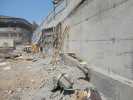
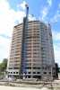
Fig. 6. General view of the construction site at the stage of excavation to the level of installation of the first layer of struts.